Control CANopen devices with USBtin
CANopen is a CAN bus protocol and specifies profiles for automation devices. USBtin can be used to control CANopen devices. Plain CAN messages are transmitted to set outputs through a Beckhoff LC5100 CANopen Coupler.Hardware setup
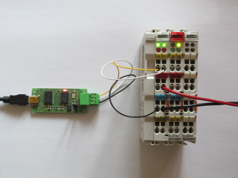
An USBtin EB is connected to a Beckhoff LC5100 with KL2134 and KL9010. The jumper for the CAN bus termination (120 ohm) on USBtin is set! Dip-swiches on the LC5100 defines the node-id and the baudrate.Hardware:
- USBtin EB - USB to CAN interface
- Beckhoff LC5100 CANopen Coupler
- KL2134, 4-channel digital output terminals
- KL9010, End terminal
Start CANopen node
After power-on the green fieldbus led (upper left led) of LC5100 blinks. This indicates the PRE-OPERATIONAL operating state. If the red CAN bus error led blinks, check the CAN bus wires and bus termination!Transmit the "Start Remote Node" command (ID 0x000, DLC 2, Data: 0x01, 0x00):
t00020100The commands were tested with USBtinViewer - Open-Source GUI for USBtin:
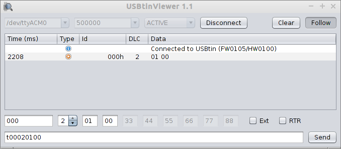
After sending the "Start Remote Node" command, the green fieldbus led on LC5100 stops blinking (permanent on) which indicates "OPERATIONAL (RUN)" mode. Now the LC5100 is ready to accept input/output commands.
Check current state of CANopen node
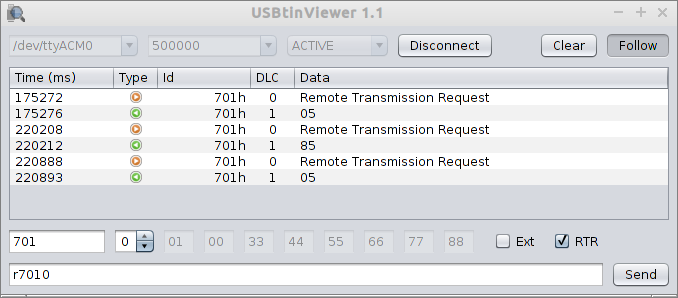
To check the state of the LC5100 a requst telegram with ID 0x700+nodeID can be sent. In this example the nodeID = 1:r7010The device responses with the current state. Bit 7 contains a toggle bit, bits 6...0 contains the node state (0x05 = operational state, 0x04 = prepared or stopped, 0x7F = pre-operational state).
Set digital outputs
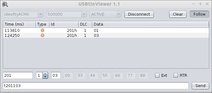
The CAN message identifier for setting digital outputs through LC5100 is 0x200+nodeID with the digital states as data payload. Example with nodeID = 1:Set Bit0:
t201101Set Bit0 and Bit1:
t201103
Links
 Technical Documentation for CANopen Coupler BK5120, BK5110, LC5100 Running CANopen devices from a Pyton script (using USBtin)